Legacy System Modernization: Remote Monitoring for a 1972 Diesel Engine
Designed and deployed a LoRa-based wireless control system enabling remote operation and real-time telemetry of a 50-year-old irrigation engine from 2+ km away. Total cost: <€150.
Bringing IoT capabilities to a 1972 diesel irrigation engine — without replacing a single component.
A custom LoRa wireless system enabling remote start/stop and real-time telemetry from 2+ km away. Deployed in production for 6+ months.
01 — The Problem
The Challenge
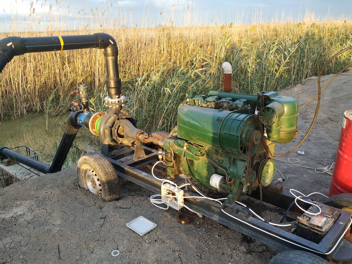
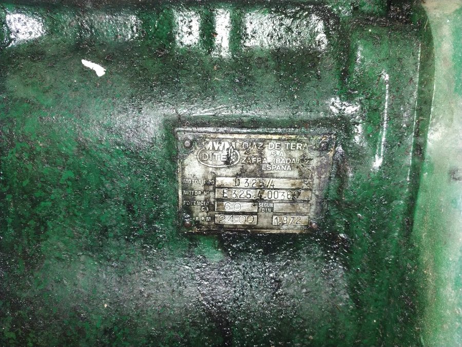
A 1972 diesel engine powers an irrigation pump on a remote farm. The engine is mechanically reliable — decades of proper maintenance have kept it running — but its complete lack of remote capability creates a serious operational bottleneck.
Every start, stop, and parameter check required a physical site visit. Oil pressure, battery voltage, engine RPM, and fuel level could only be read on-site. Missing a low-pressure event — even briefly — risks catastrophic engine damage: scored cylinder walls, seized pistons, complete overhaul.
Before
- 7 on-site visits per week for start/stop
- No remote visibility of engine parameters
- Low-pressure events detected only on-site
- €5,000+ commercial IoT solutions require engine replacement
- No historical data for predictive maintenance
After
- Remote start/stop from smartphone, 2+ km range
- Real-time telemetry: voltage, pressure, RPM, fuel
- Automated alerts on low-pressure events
- <€150 total, zero engine modifications
- 6-month deployment log for trend analysis
02 — The Solution
System Architecture
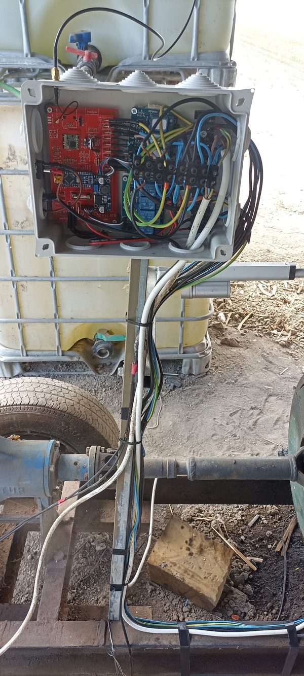
A two-node LoRa network bridges the engine to the cloud. The gateway node (ESP32 TTGO) sits within WiFi range of the farmhouse and handles bidirectional communication: relaying Blynk cloud commands to the engine, and uploading telemetry from the field. The control node (Arduino Nano + RFM95) mounts directly at the engine, reads all sensors, drives 8 relay channels, and persists state in EEPROM across power cycles.
The architecture was chosen to minimise complexity at the field end. The Arduino Nano operates without network connectivity — it only needs to drive relays and read sensors. All cloud integration is handled by the gateway, which is housed in a weatherproof enclosure near a mains power outlet.
Bidirectional LoRa communication uses addressed packets with message counters. Commands flow Gateway → Node as JSON objects keyed by virtual pin ({"V1": 1}). Telemetry flows Node → Gateway as a compact JSON array every 60 seconds, triggered after any state change or on timer.
- ESP32 TTGO LoRa v2 — dual-core, integrated LoRa + WiFi
- ATmega Arduino Nano — low power, 8 PWM pins, 8 analog
- RFM95W SX1276 LoRa chip — 868 MHz, 20 dBm TX power
- Blynk IoT cloud — virtual pins, mobile dashboard, alerts
03 — Technical Implementation
Hardware Architecture
Control Node (Arduino Nano)
- D8 Relay 1 — Engine start (pulse, 500 ms)
- D7 Relay 2 — Engine stop (pulse, 550 ms)
- D6 Relay 3 — Cooldown sequence (3 s)
- D5 Relay 4 — Oil pump / run indicator
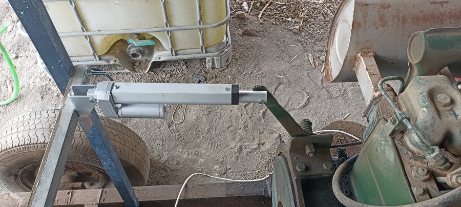
- A0 Relay 5 — Throttle (linear actuator)
- A1 Relay 6 — Brake (linear actuator)
- A2 Relay 7 — Electrovalve (fertiliser)
- A3 Relay 8 — Auxiliary output
- A7 Battery voltage (22kΩ/4.7kΩ divider)
- A6 Alternator voltage (same divider)
- A5 Oil pressure (analog transducer)
- D4 Fuel level (digital sensor)
- D3 RPM — Hall effect, INT1 interrupt
Power Supply Chain
The engine's 12 V battery powers the entire control node. A DC-DC buck converter (LM2596) steps down to 5 V for the Arduino and relays. An LDO regulator (LM1117-3.3) supplies the RFM95 LoRa module, which requires a stable 3.3 V rail.
Relay drivers use flyback diodes to suppress the inductive kick from relay coils. All sensor inputs include RC low-pass filters to reduce noise from the engine alternator.
Communication Protocol
Each command from Blynk triggers a separate LoRa packet from the gateway. The payload is a minimal JSON object keyed by virtual pin — this keeps packets small and avoids re-sending the full relay state on every interaction.
Telemetry packets from the node are sent as a JSON array (9 values, ~60 bytes), transmitted after any state change and on a 60-second timer.
// ── Gateway → Node: command packet ─────────────────────────────
// One JSON object per virtual pin trigger (Blynk BLYNK_WRITE)
{ "V1": 1 }   // Start engine (Relay 1 pulse)
{ "V2": 1 }   // Stop engine  (Relay 2 → cooldown sequence)
{ "V5": 1 }   // Throttle  (linear actuator, 1-second pulse)
{ "V6": 1 }   // Brake     (linear actuator, 1-second pulse)
{ "V24": 5 }  // RPM target (slider 0–10, mapped to 1000–75000)

// ── Node → Gateway: telemetry array ────────────────────────────
// Sent every 60 s and after any relay state change
[
  12.8,   // [0] Battery voltage (V)  — avgVoltage1
  14.1,   // [1] Alternator voltage (V) — avgVoltage2
  3.2,    // [2] Oil pressure (bar)   — avgPresion1
  0,      // [3] Electrovalve state   — LedRelay_7
  1,      // [4] Engine OFF indicator — LedRelay_3
  0,      // [5] Engine ON indicator  — LedRelay_4
  1,      // [6] Fuel level (digital) — StateLevel
  1850,   // [7] Engine RPM           — totalRPM
  5       // [8] RPM slider position  — RPM_Slider
]
The serialisation function from the actual node firmware:
// LoRaSender() — Diesel_Motor_Lora_Node/functions_rpm.h
void LoRaSender() {
  const size_t CAPACITY = JSON_ARRAY_SIZE(9);
  StaticJsonDocument<CAPACITY> doc;
  JsonArray array = doc.to<JsonArray>();

  array.add(avgVoltage1);   // battery voltage
  array.add(avgVoltage2);   // alternator voltage
  array.add(avgPresion1);   // oil pressure
  array.add(LedRelay_7);    // electrovalve state
  array.add(LedRelay_3);    // motor-off indicator
  array.add(LedRelay_4);    // motor-on indicator
  array.add(StateLevel);    // fuel level (digital)
  array.add(totalRPM);      // engine RPM
  array.add(RPM_Slider);    // RPM target slider

  char output[200];
  serializeJson(doc, output, sizeof(output));

  LoRa.beginPacket();
  LoRa.write(destination);   // 0xFF — gateway
  LoRa.write(localAddress);  // 0xBB — this node
  LoRa.write(msgCount);
  LoRa.write(sizeof(output));
  LoRa.print(output);
  LoRa.endPacket();
  msgCount++;

  onReceive(LoRa.parsePacket());  // immediately poll for reply
}
Sensor Integration
All analog readings use a 100-sample averaging loop to suppress ADC noise from the engine’s ignition system. The voltage divider formula (Vin = raw × 5V × (R1+R2) / (R2 × 1023)) is applied per-sample before accumulation.
| Sensor | Type | Pin | Conditioning |
|---|---|---|---|
| Battery voltage | Resistor divider | A7 | 22 kΩ / 4.7 kΩ → 0–5 V ADC range; 100-sample average |
| Alternator voltage | Resistor divider | A6 | Same divider; detects charging state (≈14.1 V when running) |
| Oil pressure | Analog transducer | A5 | Presion = (raw × 5000 mV × 0.0028) / 1023; 100-sample average |
| Fuel level | Digital float switch | D4 | Direct digital read — LOW = sufficient, HIGH = low fuel |
| Engine RPM | Hall effect (alternator fan) | D3 | Hardware interrupt (INT1 RISING); counted per 1-second window |
// Voltage averaging — VoltageFunction1() in functions_rpm.h
void VoltageFunction1() {
  sumVoltage1 = 0;
  for (int i = 0; i <= 100; i++) {
    int raw = analogRead(VoltageSensor);
    // Vin = (raw × 5V × (R1+R2)) / (R2 × 1023)  R1=22kΩ  R2=4.7kΩ
    float v = raw * 5.0 * (22.0 + 4.7) / (1023.0 * 4.7);
    sumVoltage1 += v;
  }
  avgVoltage1 = sumVoltage1 / 100;
}

// RPM measurement — interrupt-based, 1-second window
void ISRCountPulse3() { pulseCount3++; }

void loop_rpm() {
  if ((millis() - lastmillis) >= 1000) {
    detachInterrupt(digitalPinToInterrupt(RPM_PIN));
    unsigned long interval = millis() - lastmillis;
    // 1 pulse per rotation; multiply by 60 to convert Hz → RPM
    totalRPM = 60.0 * (pulseCount3 / (interval / 1000.0));
    lastmillis = millis();
    pulseCount3 = 0;
    attachInterrupt(digitalPinToInterrupt(RPM_PIN), ISRCountPulse3, RISING);
  }
}
Safety & Reliability
- 💾 EEPROM state persistence — engine start/stop state and electrovalve state survive power loss; restored on boot via
EEPROM.get() - ⏱ Timed relay pulses — start/stop use momentary pulses (500–550 ms) to replicate the physical key; cannot get stuck in an active state
- 🔄 Cooldown sequence — stopping triggers Relay 2 (engine off) → 5 s delay → Relay 3 (cooling run for 3 s), preventing thermal shock
- 🛡 Address-based routing — node ignores all LoRa packets not addressed to 0xBB, preventing phantom triggers from other LoRa devices
- 📡 Immediate ACK poll — after every transmission, the node calls
onReceive(LoRa.parsePacket())to catch any queued command before the next sensor cycle - 🔒 Guard conditions —
Start()only fires ifstarted == 0;OffMotor()only fires ifstarted == 1, preventing double-start and double-stop
// Start/stop state machine — loop_funtions() in functions_rpm.h
void loop_funtions() {
  started  = EEPROM.get(addr,  started);   // restore from EEPROM
  executed = EEPROM.get(addr1, executed);

  VoltageFunction1();
  VoltageFunction2();
  PressionFunction1();

  StateLevel = (!digitalRead(FuelLevel));

  // Guard: only start if not already running
  if (StateRelay_1 == 1 && started == 0) Start();

  // Guard: only stop if currently running
  if (StateRelay_2 == 1 && started == 1) OffMotor();
}

// Start() — 500 ms key pulse + EEPROM persistence
void Start() {
  digitalWrite(Relay_1, LOW);    // energise starter relay
  digitalWrite(Relay_4, LOW);    // oil pump ON
  started = 1;
  EEPROM.update(addr, started);  // persist across power cycles
  timer.setTimeout(500, turnRelay1Off);  // release after 500 ms
}

// Stop sequence: stop pulse → 5 s → 3 s cooldown
void OffMotor() {
  digitalWrite(Relay_2, LOW);
  started = 0;
  EEPROM.update(addr, started);
  timer.setTimeout(550, turnRelay2Off);   // release stop relay
  // turnRelay2Off() → setTimeout(5000, turnRelay3ON)
  // turnRelay3ON()  → setTimeout(3000, turnRelay3OFF)
}
04 — Results & Impact
Outcomes
Key Metrics — 6 months production deployment
System uptime
Site visits / week
Wireless range achieved
Low-pressure events caught
Total hardware cost
Engine modifications
05 — Technical Deep Dive
Component Specifications
| Gateway MCU | ESP32 TTGO LoRa v2 (dual-core 240 MHz, 4 MB flash) |
| Node MCU | Arduino Nano — ATmega328P, 16 MHz, 32 KB flash, 2 KB SRAM |
| LoRa Module | RFM95W — SX1276, 868 MHz ISM band |
| TX Power | 20 dBm (100 mW) — max legal limit EU 868 MHz |
| LoRa Bandwidth | 125 kHz · SF7 · CR 4/5 |
| Range (tested) | 2.3 km, rural terrain, no line of sight |
| Telemetry interval | 60 s + event-triggered after any relay change |
| Relay outputs | 8× SPDT 10 A 250 VAC — start, stop, cooldown, oil pump, throttle, brake, valve, aux |
| Power rail | 12 V battery → LM2596 buck (5 V, 3 A) → LM1117-3.3 LDO (3.3 V, 800 mA) |
| Voltage sensing | 22 kΩ / 4.7 kΩ resistor divider, 100-sample ADC average |
| Pressure sensing | Analog transducer 0–10 bar, calibration: raw × 5000 mV × 0.0028 / 1023 |
| RPM sensing | Hall effect on alternator fan, hardware interrupt (INT1), 1 s counting window |
| State persistence | ATmega328P EEPROM (1 KB), updated on every state change |
| Cloud platform | Blynk IoT — virtual pins V1–V24, LED widgets, value displays |
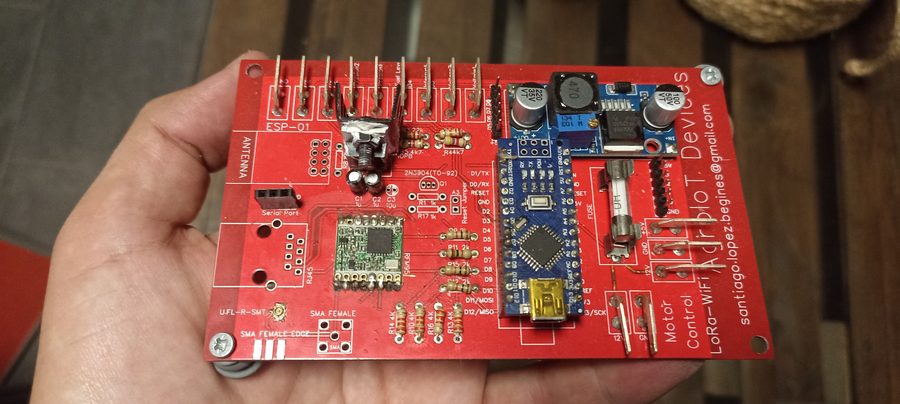
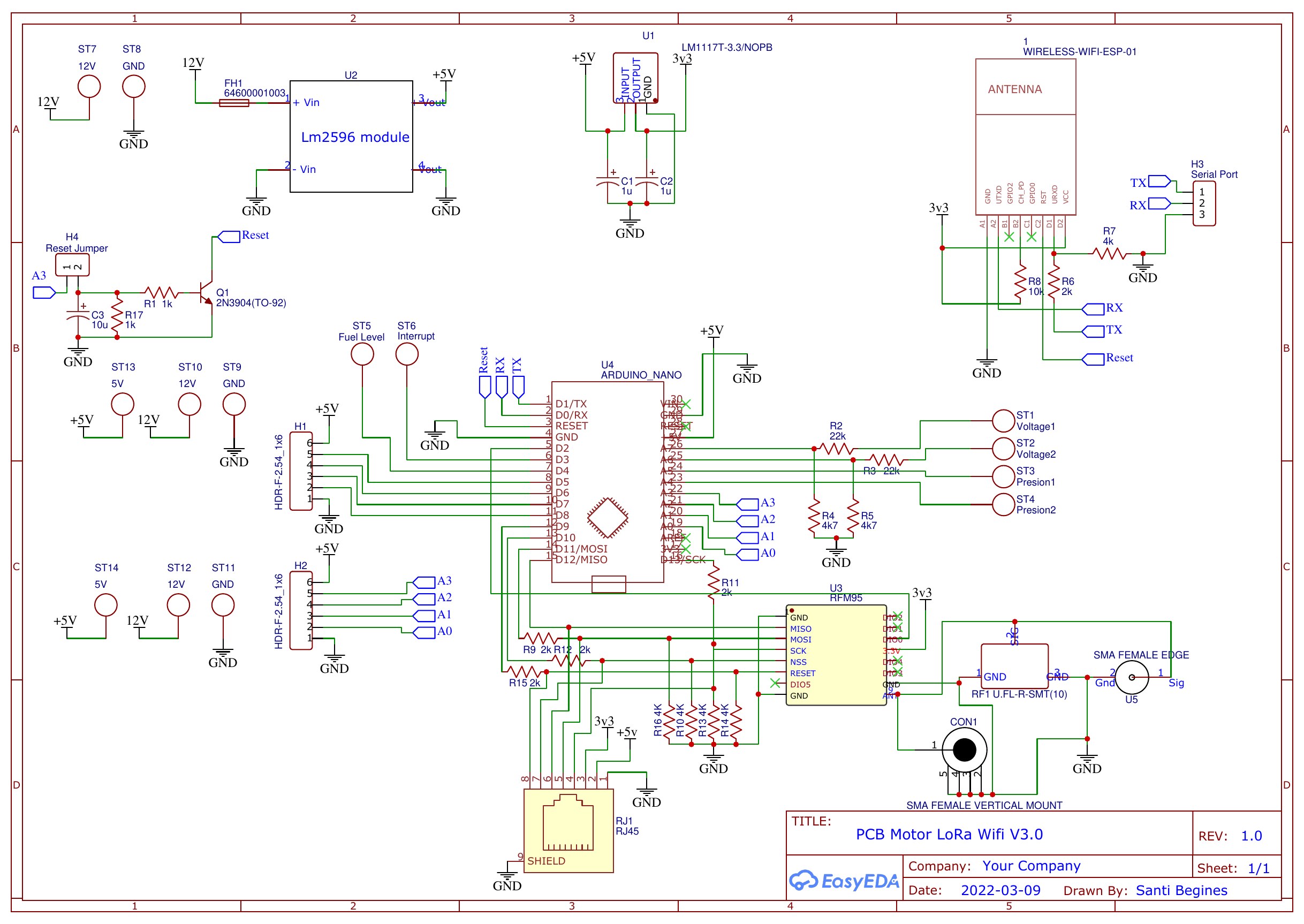
| PCB | Custom 2-layer, screw terminals, ground plane, flyback diodes on relay coils |
PCB Schematic — V3.0
06 — Skills & Technologies
Technologies Used
07 — Next Steps
Planned Improvements
Interested in similar work?
This project demonstrates the same skills required for medical device integration, laboratory automation, and embedded telemetry in regulated environments — sensor conditioning, reliable wireless protocols, state persistence, and non-invasive retrofitting to legacy hardware.